


Another monster tank....the IS-4
 02-04-2023 | 03:08 PM
#1
Thread Starter

My Feedback: (1)
Since I already showed it in the IS-7 thread I thought it might get some space of it's own.
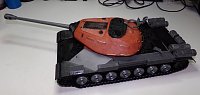
And after 9.5 hours of print time and 195G (mostly supports) of filament later...a turret emerges. Yes, I tried tree supports and got two 6 hour in failed prints as the tree supports would come off the bed mid print.


Here it is almost all cleaned up from the supports which was a PITA BTW. PETG supports are notoriously hard to get off. The support surfaces are really rough, but they won't show in the finished tank.


And of course a side by side of the two brothers from two different mothers:

Printer is already hard at work on more parts.
Derek
And after 9.5 hours of print time and 195G (mostly supports) of filament later...a turret emerges. Yes, I tried tree supports and got two 6 hour in failed prints as the tree supports would come off the bed mid print.
Here it is almost all cleaned up from the supports which was a PITA BTW. PETG supports are notoriously hard to get off. The support surfaces are really rough, but they won't show in the finished tank.
And of course a side by side of the two brothers from two different mothers:
Printer is already hard at work on more parts.
Derek
 02-04-2023 | 03:38 PM
#2

Have you thought about slicing the turret horizontally into maybe three or four pieces to avoid the supports? Print the top part with only a small portion of the sides. Then print the side sections, since they are angled they may be able to print without supports. When all are done glue together. I have a Sherman turret I need to print for a 1/6 scale tank. Printing the turret whole is like three days. I thought of this to make it more manageable.
03-11-2023 | 11:31 AM
#5
Thread Starter
My Feedback: (1)
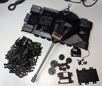
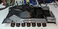
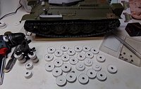
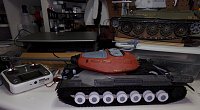
Made quite a bit of progress on this guy recently. At least most of the major components are printed. After doing the initial assembly I really didn't like the fit of the deck to the sides so I reprinted the sides from the new Sunlu PETG-G I got. The Bambu had a few firmware updates that seemed to fix the initial issues I had printing them so I was able to print them as one piece now. The fit is so much better. This is how she stands at the momemt. That pile is 160+ track pieces. Not a lot of post processing done yet. I wanted to get the mechanicals and physical build out of the way before disassembling it to do the finishing work.
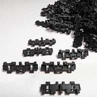
Better shot of the track quality. Printed them 54 at a time and it took 6.5 hours per sheet at a 0.08 layer height. They were printed at an angle so that both sides had good surface quality. Only supports used were specified as "critical areas" and only touching the bed. They came out quite nice. I can't assemble them until my spring steel wire arrives on the slow boat from China.
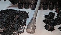
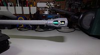
Close up of the muzzle brake:
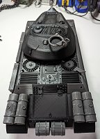
View of the suspension. I have some gearboxes arriving today so I can get the sprockets mounted soon.
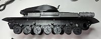
Another side view.
Rear view.
Better shot of the track quality. Printed them 54 at a time and it took 6.5 hours per sheet at a 0.08 layer height. They were printed at an angle so that both sides had good surface quality. Only supports used were specified as "critical areas" and only touching the bed. They came out quite nice. I can't assemble them until my spring steel wire arrives on the slow boat from China.
Close up of the muzzle brake:
View of the suspension. I have some gearboxes arriving today so I can get the sprockets mounted soon.
Another side view.
Rear view.
The following users liked this post:
RichJohnson (03-11-2023)
03-11-2023 | 07:24 PM
#6

Maybe have a look at Resin 3D Printing some of the more intricate parts? 🤔
Generally I'd be doing literally everything that isn't the size of the Hull and Turret on my SLA 3D Printer but especially the Tracks and stuff like the Muzzle Break came to mind.
Just get yourself one of those Vortex IPA Cleaning Stations to let it deal with the mess of getting the remaining uncured Gunk off a freshly 3D Printed Part and it'll be hardly an issue dealing with mSLA vs. FDM.
Any shots of how your FDM Tracks were oriented while still on the Build Plate? Kinda curious how you oriented the Layers in order to deal with the Pins not getting stripped out of the Links or the Track splitting apart in the middle or at the Ends😁
03-11-2023 | 08:05 PM
#7
Thread Starter
My Feedback: (1)
I actually have a resin printer sitting in the closet right now with a wash/cure station...both new in the box. I haven't had the time to set it up and play with it yet. I haven't printed some of the really small details as of yet because of that.

Orientation

Sliced
Derek
Orientation
Sliced
Derek
03-12-2023 | 02:19 PM
#8

Very nice, I can't wait to see them finished! I love the aesthetics of the IS series. I have a Juckenburg IS-3 kit I'm going to get restarted later this year after I get a couple other projects finished. How is the overall build quality on Inkor's IS-4, I have his C1 Ariete that I'm hoping to start printing soon.
03-12-2023 | 03:18 PM
#9
Thread Starter
My Feedback: (1)
I purchased the Ariete also, but haven't started printing it yet. Overall things fit together really well. There is an area around the driver's hatch where the hump isn't connected to the armor plate, but that is pretty easily fixed with some glue and left over support plastic. The issues I have with a both the Hellcat and the IS-4 is gearbox maintenance. The gearboxes are going to be really hard to remove for maintenance after the builds are complete. For the Hellcat, they are mounted under the front glacis plate. Problem with that is that the light guards for the tank extend from that plate to the lower plate. That means you can't glue the lower parts of the guards to the lower plate or you won't be able to remove the gearboxes at all. With the IS-4, the motors are under the rear plate. You can remove the gearboxes but you would have to remove about a dozen screws to do it. I was planning on trying to glue a lot of the panels together, but for maintenance I will probably have to leave a lot of them just screwed together. There are some areas where hatches aren't supported from underneath. Not hard to fix - just need to glue some flat stock under the edges of the hatch to keep it from closing too far.
I also thought that the Taigne mid/low gearboxes were a decent price point and build quality that would work with these tanks. They fit in the tanks fine with some slight plastic grinding, but the mounting holes don't line up right. Since Inkor made the screw hole area only slightly bigger than the hole itself I will probably have to elongate the mounting holes on the Taigen gearboxes to make them work. It's like the mounting holes are 2mm too close to the outside hull wall. Being short shaft gearboxes, they have to be butted right against the hull walls to have enough of the shaft to mount the sprockets. It's the same issue in both the Hellcat and the IS-4.
I wish the idlers, road wheels, and return rollers were spec'd to use bearings. I may try to add bearings to as many of the tanks as I can to reduce wear of plastic on metal shafts.
So basically the designs don't have maintenance considered.
Derek
11-12-2023 | 03:34 AM
#10
Thread Starter
My Feedback: (1)
Worked on the IS-4 a bit today. Still lots of printer lines to hide, but it's coming along nicely. Got motors, elevation, recoil, high intensity flash, turret handles, and tracks installed. Just getting everything mocked up. Been adding the red glazing putty with an old paintbrush so it's going on more consistent and easier to sand down.

The following users liked this post:
PE YOUNG (11-12-2023)
11-15-2023 | 12:44 PM
#11
Wow, nice build. Thanks for sharing!!!
The following users liked this post:
tankme (11-15-2023)
01-06-2024 | 05:54 AM
#12
Thread Starter
My Feedback: (1)
Been busy working on multiple projects, but made progress on this guy. I have been getting much better with the Bambu slicer so I took advantage of that. I have always hated that Inkor's designs don't incorporate bearings in anything. The road wheels he designs also have saving filament in mind so the inner wheels usually have vast open spaces in them with small hubs. The hubs are usually too small for bearings in some cases. I decided to fix these "issues (for me)". First off, I filled in the backs of the wheel to give the bearing more support. Secondly, I modified the road wheel STL to accept a 3mm bore x 7mm x 2.5mm flanged (8mm flange) bearing. Then I reprinted the wheels out of ASA to get more detail with less post processing. Don't mind the secret project bogie truck in the picture... :shh:
With numerous successful resin prints under my belt, I added a bunch of resin details to the tank. They are not permanently attached at the moment. The new wheels run smooth on their new bearings. I will be updating the idler also. Currently I'm reprinting some of the upper deck parts in ASA to enhance the detail. I can now print ASA freely as the printer now lives in the garage. Makes me wish I hadn't printed so many parts before moving the printer. PETG is great for strength, but less so for detail. And also now that the resin printer is working, I'm going to be printing tracks for some tanks in resin.
That's all for now...
01-21-2026 | 05:04 PM
#13
Thread Starter
My Feedback: (1)
Work stopped on this vehicle for a while, but I've been working on it recently. I hadn't updated this thread in a while so I thought it was time to bring it up to speed:
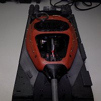
The IS-4 was one of the first tanks I started 3D printing so I decided it was high time to make progress on this project. I grabbed one of the Heng Long plastic dual diff gearboxes out of the stash since this is a fairly light tank with all plastic running gear. I knew it was going to be a really tight fit back there. Like I did with the Kranvagn, I wanted to give the plastic gears all the help I could so I designed and 3D printed some bearing holders to be attached to the outside of the hull inside the outdrive housing. This gives the gearbox shafts support all the way out to the sprocket. It took quite a bit of fitting to get everything to line up correctly. I also poured some resin into the gearbox mounts to just make sure there was a solid mounting for the gearbox. I had previously installed some traditional gearboxes in the tank, but they were really difficult to remove if I need to do any maintenance. Believe it or not the dual diff gearbox is easier to remove. I did have to shorten the gearbox shafts to make them line up properly.

Gearbox shoehorned in the hull.

After fighting for 2 days getting the gearbox in and running properly, I buttoned the tank up, added a bunch of the resin printed parts, sanded a bunch of layer lines off, and then threw some primer on the whole tank to see where I was at. It seems there are still some layer lines so I will sand them lightly and reprime. Looking at some IS-4 walk around, there is some additional texture and weld lines that need to be added. Having it all one color really gave me a nice warm and fuzzy to get the project finished. Still lots of work to do, but it's starting to look really good. Somehow I destroyed a could of teeth on one of the sprockets so those will both be reprinted in a better material once my printer is repaired. I guess the 8900 hours of printing has actually worn out my extruder servo motor. :'(


Installed some fully functional spare track hangers using some brass bolts both front and rear. They are screwed into the plastic so they can actually be removed and the track pads are functional replacements for the tracks on this tank. The tracks were printed in ASA so we shall see how well they hold up. Figured I could do some detail work while waiting for the printer parts.


Started adding the weld lines around the front of the tank. It helps cover up the joints of the 3D prints plus highlights the actual construction of the tank.

Used some contact cement to install the wheel hub caps which were printed in resin. Currently shopping for a better resin printer. Mine works fine...sometimes.

The rear deck was screaming for some protective screens on the fans and rear grates. Cut them out of some old window screen I have in the scratch building material box.

I cleaned up the last of the print lines on the front end along with finishing the blending of the front fenders complete with fake bolt details.

I also started to do the weld details on the turret. The weld line will go all the way around the removable roof of the turret. It will help hide the separation and still allow me to remove it to work on the turret insides. Plus it's a weld line that's supposed to actually be there.

Continued in the next post...
The IS-4 was one of the first tanks I started 3D printing so I decided it was high time to make progress on this project. I grabbed one of the Heng Long plastic dual diff gearboxes out of the stash since this is a fairly light tank with all plastic running gear. I knew it was going to be a really tight fit back there. Like I did with the Kranvagn, I wanted to give the plastic gears all the help I could so I designed and 3D printed some bearing holders to be attached to the outside of the hull inside the outdrive housing. This gives the gearbox shafts support all the way out to the sprocket. It took quite a bit of fitting to get everything to line up correctly. I also poured some resin into the gearbox mounts to just make sure there was a solid mounting for the gearbox. I had previously installed some traditional gearboxes in the tank, but they were really difficult to remove if I need to do any maintenance. Believe it or not the dual diff gearbox is easier to remove. I did have to shorten the gearbox shafts to make them line up properly.
Gearbox shoehorned in the hull.
After fighting for 2 days getting the gearbox in and running properly, I buttoned the tank up, added a bunch of the resin printed parts, sanded a bunch of layer lines off, and then threw some primer on the whole tank to see where I was at. It seems there are still some layer lines so I will sand them lightly and reprime. Looking at some IS-4 walk around, there is some additional texture and weld lines that need to be added. Having it all one color really gave me a nice warm and fuzzy to get the project finished. Still lots of work to do, but it's starting to look really good. Somehow I destroyed a could of teeth on one of the sprockets so those will both be reprinted in a better material once my printer is repaired. I guess the 8900 hours of printing has actually worn out my extruder servo motor. :'(
Installed some fully functional spare track hangers using some brass bolts both front and rear. They are screwed into the plastic so they can actually be removed and the track pads are functional replacements for the tracks on this tank. The tracks were printed in ASA so we shall see how well they hold up. Figured I could do some detail work while waiting for the printer parts.
Started adding the weld lines around the front of the tank. It helps cover up the joints of the 3D prints plus highlights the actual construction of the tank.
Used some contact cement to install the wheel hub caps which were printed in resin. Currently shopping for a better resin printer. Mine works fine...sometimes.
The rear deck was screaming for some protective screens on the fans and rear grates. Cut them out of some old window screen I have in the scratch building material box.
I cleaned up the last of the print lines on the front end along with finishing the blending of the front fenders complete with fake bolt details.
I also started to do the weld details on the turret. The weld line will go all the way around the removable roof of the turret. It will help hide the separation and still allow me to remove it to work on the turret insides. Plus it's a weld line that's supposed to actually be there.
Continued in the next post...
01-21-2026 | 05:06 PM
#14
Thread Starter
My Feedback: (1)
Then I ran into a bit of snag with this build:
When the original sprockets I printed shed a sprocket tooth, I printed another set in PETG hoping that it was the fact the old ones were in a more fragile material. Long story short, the new PETG sprockets have shed teeth and I haven't even put any power to them yet. It's kinda why this build stalled.
I have a plan though:
Since I've been test printing the new KV-1/KV-85 tanks Inkor is releasing, I found that he used the same basic track STLs for the IS-4 and the KV-1. The KV-1 sprockets fit my previously printed IS-4 tracks perfectly. The only difference was that he made the center guide tooth higher and slightly hollow on the KV version track. The KV sprocket teeth are much beefier than the ones in the IS-4 file set. The IS-4 tank was one of his earlier designs and not many have built the tank (that I've seen) and no one has printed a make of it on the Cults 3D website. Technically the KV tracks are narrower than the IS-4 tracks. I'm guessing he decided to forgo redesigning them for the KV to save on CAD time. I haven't gotten a response as to whether or not he will make the KV tracks more narrow, but that's kinda off topic. I'm not a CAD master so I can't just make the teeth stronger in CAD for the IS-4. I can however try to use my Bambu slicer skills to make the teeth wider. I'm going to attempt to slice the sprocket teeth off, widen that section, and then reattach that to the sprocket hub using the slicer tools. It should give me the extra tooth strength I'm looking for while still interfacing with the track correctly. The STL file made from my slicer fu will look strange and might take a few tries to get it right, but in the end I think it will be worth the boost in reliability.
I took the slicer and cut off the end of the sprocket:

With it sliced off, I increased the thickness of the sprocket ring and removed the center section that got cut off off the old sprocket.

I drug a new copy of the original sprocket onto the build plate. It then duplicated the ring I made thicker and overlayed it to the top and bottom set of sprocket teeth. All of this was done with the sprocket sitting vertically because you can right click on any item on the build plate choosing "center". It perfectly centers it on the plate. After centering the original sprocket, I centered both the sprocket rings which made them line up in exactly the right orientation getting rid of any guess work. The slicer doesn't allow you to elevate or depress the sprocket rings I cut off so I left them on the build plate (flat), I moved the unmodified sprocket below the build plate and merged it with the thicker sprocket once it where I wanted it. I did the same process with the other sprocket ring so that both rings were merged. I had a copy of the KV-1 sprocket on the build plate so that I new exactly how thick the ring had to be. You can see that the only thing that changed was the thickness of the teeth.

And the final product after printing. As you can see, the teeth are now beefier. They should hold up much better now.

I guess without knowing something about the way the slicer works it's probably Greek for some. The Bambu slicing software allows some pretty powerful functions where you can create shapes like boxes, cylinders, circles, discs, rounded rectangles, cones, etc. You can combine a lot of those things together and "merge" them into a single part. You can also draw "negatives" of all those items which basically cut holes instead of create solid objects. As an example, I needed a speaker box for the IS-4 as there isn't a lot of space in it. The Heng Long 7.1 seems to keep blowing my Taigen speakers so I grabbed a Visaton FRS 5X 2" speaker I had in the stash. That meant I needed a box that fit in the hull for that speaker so I ended up drawing one in the slicer that fit the space and the speaker. I also ported the box and integrated the porting tube into the lid. I didn't measure out the mounting holes for the speaker or draw the holes in the main box. I'll just use a drill for those. I printed it in a really fast draft mode so it's not the prettiest thing, but it doesn't have to be. The gray part the arrow is pointing to is a "negative" cylinder to make the port tube hollow when it prints.
As drawn in the slicer:

And with the speaker mounted and installed. The battery will be mounted in the nose of the tank.

The provided straps for the unditching log were rather basic so I used some of my fabrication skills to fashion some new mounts out of some left over brass and aluminum can for the straps. See, I don't have to 3D print everything. The log is just some 5/8" dowel rod I picked up at Walmart one night. I also decided that I didn't like the solid tow shackle holder and made a new one out of brass.


Then I did print some tow cable ends and added some steel cable to make my own tow cables. I used some more of that brass sheet and some square styrene bar to fabricate the tow cable tie down points on the front and rear of the tank. Each one is held to the tank with a small brass bolt. I also added the mounting angle iron on the front fenders that would be used to locate the stove/heater thing that I'm not going to mount there. Didn't really care for how it looked and the part wasn't that detailed regardless.


The tow cable mounts wouldn't be complete without the guide pins and holders fabricated out of brass rod and some spring steel rod leftovers.

On the rear end, I added some resin printed tools, resin printed smoke dischargers and mocked up the location of the resin printed supplemental fuel tanks. The first pic shows the lack of detail on the parts that came with the STL files for the tank and the second pic has the more detailed resin pieces depicted.


I had heard of quality issues with these plastic Heng Long PDSGB type gearboxes, but my Kranvagn gearbox was running great so I bought a few more. I also figured they were so cheap at $60 when I bought them that I would take a chance. I bought like 4 of them so I figured that I could keep at least two of the running with parts from the other ones. All was going well until I got the main wiring done. I fired up the tank for a test drive and the gearbox was acting weird and making some strange noises when I tried to turn the tank. I ripped the gearbox out and found that the first stage of the reduction was missing teeth in one spot and the teeth in an another area were worn down.

At this point, I wanted to QC what was in the other plastic gearboxes. Upon opening the 3rd plastic gearbox I found that the second stage gear in that gearbox was actually the completely wrong gear from the HL factory. The bore was oversized so it wobbled on the shaft and it was supposed to be a double gear. Instead it was a single gear with a smooth hub. Before even installing it I found out that it would never turn the tank. A metal replacement gear for that one has been found, but not at an economical price so the search continues to get that one running. I doubt I can log a complaint to Toucan as I've had these gearboxes for a very long time before using them. Since I had a metal version of this gearbox in my stash, I opened it up and stole the first gear reduction out of it and installed it in the plastic gearbox. I did this because I found a replacement gear on AliExpress and ordered enough of them to replace all the plastic first stage gears in all my gearboxes and a few extras just in case.

Anyway, after replacing the failed first stage gear with a metal one, the tank ran great. I'm still waiting for the metal first stage gears to arrive, but they should be here in time to install in my other projects. The gears I found for the first stage are these in case anyone else has had a failure of that stage on one of these plastic HL gearboxes:
https://www.aliexpress.us/item/32568...yAdapt=glo2usa

And now the thread is caught up...
When the original sprockets I printed shed a sprocket tooth, I printed another set in PETG hoping that it was the fact the old ones were in a more fragile material. Long story short, the new PETG sprockets have shed teeth and I haven't even put any power to them yet. It's kinda why this build stalled.
I have a plan though:
Since I've been test printing the new KV-1/KV-85 tanks Inkor is releasing, I found that he used the same basic track STLs for the IS-4 and the KV-1. The KV-1 sprockets fit my previously printed IS-4 tracks perfectly. The only difference was that he made the center guide tooth higher and slightly hollow on the KV version track. The KV sprocket teeth are much beefier than the ones in the IS-4 file set. The IS-4 tank was one of his earlier designs and not many have built the tank (that I've seen) and no one has printed a make of it on the Cults 3D website. Technically the KV tracks are narrower than the IS-4 tracks. I'm guessing he decided to forgo redesigning them for the KV to save on CAD time. I haven't gotten a response as to whether or not he will make the KV tracks more narrow, but that's kinda off topic. I'm not a CAD master so I can't just make the teeth stronger in CAD for the IS-4. I can however try to use my Bambu slicer skills to make the teeth wider. I'm going to attempt to slice the sprocket teeth off, widen that section, and then reattach that to the sprocket hub using the slicer tools. It should give me the extra tooth strength I'm looking for while still interfacing with the track correctly. The STL file made from my slicer fu will look strange and might take a few tries to get it right, but in the end I think it will be worth the boost in reliability.
I took the slicer and cut off the end of the sprocket:
With it sliced off, I increased the thickness of the sprocket ring and removed the center section that got cut off off the old sprocket.
I drug a new copy of the original sprocket onto the build plate. It then duplicated the ring I made thicker and overlayed it to the top and bottom set of sprocket teeth. All of this was done with the sprocket sitting vertically because you can right click on any item on the build plate choosing "center". It perfectly centers it on the plate. After centering the original sprocket, I centered both the sprocket rings which made them line up in exactly the right orientation getting rid of any guess work. The slicer doesn't allow you to elevate or depress the sprocket rings I cut off so I left them on the build plate (flat), I moved the unmodified sprocket below the build plate and merged it with the thicker sprocket once it where I wanted it. I did the same process with the other sprocket ring so that both rings were merged. I had a copy of the KV-1 sprocket on the build plate so that I new exactly how thick the ring had to be. You can see that the only thing that changed was the thickness of the teeth.
And the final product after printing. As you can see, the teeth are now beefier. They should hold up much better now.
I guess without knowing something about the way the slicer works it's probably Greek for some.
The Bambu slicing software allows some pretty powerful functions where you can create shapes like boxes, cylinders, circles, discs, rounded rectangles, cones, etc. You can combine a lot of those things together and "merge" them into a single part. You can also draw "negatives" of all those items which basically cut holes instead of create solid objects. As an example, I needed a speaker box for the IS-4 as there isn't a lot of space in it. The Heng Long 7.1 seems to keep blowing my Taigen speakers so I grabbed a Visaton FRS 5X 2" speaker I had in the stash. That meant I needed a box that fit in the hull for that speaker so I ended up drawing one in the slicer that fit the space and the speaker. I also ported the box and integrated the porting tube into the lid. I didn't measure out the mounting holes for the speaker or draw the holes in the main box. I'll just use a drill for those. I printed it in a really fast draft mode so it's not the prettiest thing, but it doesn't have to be. The gray part the arrow is pointing to is a "negative" cylinder to make the port tube hollow when it prints.As drawn in the slicer:
And with the speaker mounted and installed. The battery will be mounted in the nose of the tank.
The provided straps for the unditching log were rather basic so I used some of my fabrication skills to fashion some new mounts out of some left over brass and aluminum can for the straps. See, I don't have to 3D print everything.
The log is just some 5/8" dowel rod I picked up at Walmart one night. I also decided that I didn't like the solid tow shackle holder and made a new one out of brass.Then I did print some tow cable ends and added some steel cable to make my own tow cables. I used some more of that brass sheet and some square styrene bar to fabricate the tow cable tie down points on the front and rear of the tank. Each one is held to the tank with a small brass bolt. I also added the mounting angle iron on the front fenders that would be used to locate the stove/heater thing that I'm not going to mount there. Didn't really care for how it looked and the part wasn't that detailed regardless.
The tow cable mounts wouldn't be complete without the guide pins and holders fabricated out of brass rod and some spring steel rod leftovers.
On the rear end, I added some resin printed tools, resin printed smoke dischargers and mocked up the location of the resin printed supplemental fuel tanks. The first pic shows the lack of detail on the parts that came with the STL files for the tank and the second pic has the more detailed resin pieces depicted.
I had heard of quality issues with these plastic Heng Long PDSGB type gearboxes, but my Kranvagn gearbox was running great so I bought a few more. I also figured they were so cheap at $60 when I bought them that I would take a chance. I bought like 4 of them so I figured that I could keep at least two of the running with parts from the other ones. All was going well until I got the main wiring done. I fired up the tank for a test drive and the gearbox was acting weird and making some strange noises when I tried to turn the tank. I ripped the gearbox out and found that the first stage of the reduction was missing teeth in one spot and the teeth in an another area were worn down.
At this point, I wanted to QC what was in the other plastic gearboxes. Upon opening the 3rd plastic gearbox I found that the second stage gear in that gearbox was actually the completely wrong gear from the HL factory. The bore was oversized so it wobbled on the shaft and it was supposed to be a double gear. Instead it was a single gear with a smooth hub. Before even installing it I found out that it would never turn the tank. A metal replacement gear for that one has been found, but not at an economical price so the search continues to get that one running. I doubt I can log a complaint to Toucan as I've had these gearboxes for a very long time before using them. Since I had a metal version of this gearbox in my stash, I opened it up and stole the first gear reduction out of it and installed it in the plastic gearbox. I did this because I found a replacement gear on AliExpress and ordered enough of them to replace all the plastic first stage gears in all my gearboxes and a few extras just in case.
Anyway, after replacing the failed first stage gear with a metal one, the tank ran great. I'm still waiting for the metal first stage gears to arrive, but they should be here in time to install in my other projects. The gears I found for the first stage are these in case anyone else has had a failure of that stage on one of these plastic HL gearboxes:
https://www.aliexpress.us/item/32568...yAdapt=glo2usa
And now the thread is caught up...
Last edited by tankme; 01-22-2026 at 02:14 AM. Reason: Adding pics
01-26-2026 | 04:11 AM
#15
Thread Starter
My Feedback: (1)
Progress has been a little slow lately. Initial driving tests went well after getting the gearbox gears replaced. The power switch is mounted under the driver's hatch:

I also found some clear lenses on AliExpress in 10mm and 12mm sizes that I decided to use for the headlight:
https://www.aliexpress.us/item/32568...yAdapt=glo2usa
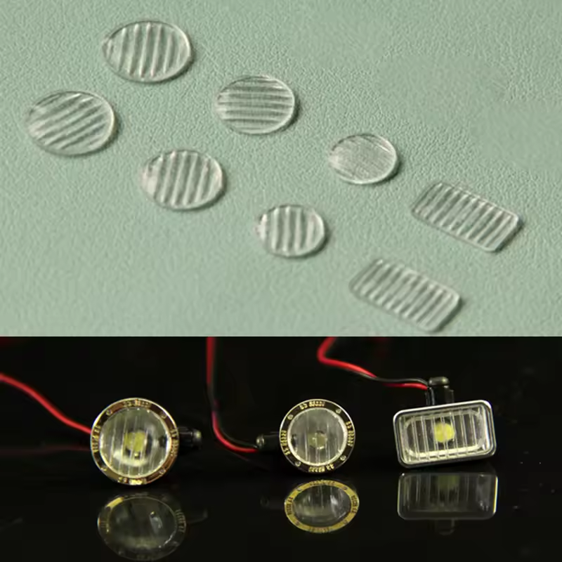
installed on the front headlight using some Testors canopy glue. I didn't have a 3mm warm white LED so I ended up installing a yellow one, but I may change it out before the end of the build. I also painted the inside of the light with chrome paint. I added the mounting brackets for the fender tool box.


I started to do the finishing details on the rear deck. Each one of the upper deck panels had the handles added and the lifting eyes were fabricated. I also filled the old fuel tank mounting holes, I started finishing the brass work on the fuel holders, and installed the extended hinge pin for the engine deck as seen on the IS-4 in Kubinka. The convoy lights were painted black because they will be functional and the black paint helps mitigate the light bleed. I was able to put some 0604 LEDs in them by drilling out the lighting housings. The rears are red and the fronts are green LEDs. They have been tested, but the wiring isn't completely finished.


And that's all for now...
I also found some clear lenses on AliExpress in 10mm and 12mm sizes that I decided to use for the headlight:
https://www.aliexpress.us/item/32568...yAdapt=glo2usa
installed on the front headlight using some Testors canopy glue. I didn't have a 3mm warm white LED so I ended up installing a yellow one, but I may change it out before the end of the build. I also painted the inside of the light with chrome paint. I added the mounting brackets for the fender tool box.
I started to do the finishing details on the rear deck. Each one of the upper deck panels had the handles added and the lifting eyes were fabricated. I also filled the old fuel tank mounting holes, I started finishing the brass work on the fuel holders, and installed the extended hinge pin for the engine deck as seen on the IS-4 in Kubinka. The convoy lights were painted black because they will be functional and the black paint helps mitigate the light bleed. I was able to put some 0604 LEDs in them by drilling out the lighting housings. The rears are red and the fronts are green LEDs. They have been tested, but the wiring isn't completely finished.
And that's all for now...
02-07-2026 | 05:24 AM
#16
Thread Starter
My Feedback: (1)
Quite a few updates this weekend. Getting close to finished now.
I did finally get all the convoy lights wired up and working. Green is in the front and red in the rear.


One side of the extra fuel barrels mounted


Barrels fully mounted.

Barrel LED mounted and wired up.

Saw and mounting rails added.

Antenna mount created in the slicer, printed and mounted. Secondary exhaust fan added.


Added the hatch helper springs. The don't interfere with opening the hatches at all. More weld beads added. Replaced some of the fuel filler doors and fain access doors with some that looked more representative of the real ones that I drew up in the slicer.


I've got some additional wiring to do in the mantlet (IR LED and MG LED), the battle system apple mount needs to be added, and then I think this is going off to paint.
That's all for now...
I did finally get all the convoy lights wired up and working. Green is in the front and red in the rear.
One side of the extra fuel barrels mounted
Barrels fully mounted.
Barrel LED mounted and wired up.
Saw and mounting rails added.
Antenna mount created in the slicer, printed and mounted. Secondary exhaust fan added.
Added the hatch helper springs. The don't interfere with opening the hatches at all. More weld beads added. Replaced some of the fuel filler doors and fain access doors with some that looked more representative of the real ones that I drew up in the slicer.
I've got some additional wiring to do in the mantlet (IR LED and MG LED), the battle system apple mount needs to be added, and then I think this is going off to paint.
That's all for now...
02-13-2026 | 01:35 AM
#17
Thread Starter
My Feedback: (1)
I finished the IR LED, the battle system mount, and painted this piglet. I created a custom mount for the LegoDEI IR receiver in the loaders vision periscope. I carefully drilled all the way around it so that I could remove it. The mount is held in with two screws so it can be removed and replaced with the periscope if I am not battling it.


In the paint booth.

And here she is painted up. Still need to paint the wheel rims with silver, but I needed the tank ready to battle this weekend. I'll finish the weathering and detail work after the battle weekend. It's indoor so it should be no worse for wear.


That's all for now...
I created a custom mount for the LegoDEI IR receiver in the loaders vision periscope. I carefully drilled all the way around it so that I could remove it. The mount is held in with two screws so it can be removed and replaced with the periscope if I am not battling it.In the paint booth.
And here she is painted up. Still need to paint the wheel rims with silver, but I needed the tank ready to battle this weekend. I'll finish the weathering and detail work after the battle weekend. It's indoor so it should be no worse for wear.
That's all for now...


